Lab 11 · Lasers and linksDesign a Vernier Tunable Laser
Model the two-ring filter of a silicon external-cavity laser, let the gain pick its lasing mode, map its tuning against the two heaters, then choose ring radii and coupling for a tuning range and a side-mode margin.
- compute an add-drop ring’s drop response, free spectral range, linewidth and finesse;
- combine two rings into a Vernier filter and find where their resonance combs coincide;
- pick the lasing cavity mode from the gain and the round-trip filter, and measure its margin over the next supermode;
- map the lasing wavelength against the two heaters, and find the heater power per step;
- choose radii and coupling for a given tuning range and side-mode suppression.
What you need
- Chapter 26 (Sections 26.4 and 26.5), with the add-drop ring of Chapter 12 (Sections 12.3 and 12.4) and the heaters of Chapter 18.
- Python 3.11 or newer with NumPy and Matplotlib:
pip install numpy matplotlib. - The script
lab11_vernier.py(also in the repository’slabs/folder). - About two hours, including the exercises.
Run it from a terminal in the folder where you saved it:
python lab11_vernier.py
It prints a checkpoint for each part below, with the value from the chapter or its demo beside it, and saves the figure lab11_vernier.png in a few seconds. Read each part, then the matching function in the script; change things and run it again. Wavelengths and radii are in micrometres inside the script, heater powers in milliwatts.
The laser is the one of the Chapter 26 demo: a III–V gain chip feeds a bus waveguide; ring 1 drops the light into a second waveguide, ring 2 drops it into a third, and a loop mirror sends it back the same way. The rings are 500 × 220 nm silicon strips (\(n_\mathrm{eff} = 2.446\), \(n_g = 4.18\) at 1550 nm) with 3 dB/cm of loss, and the whole cavity is about 2.5 mm long with an average group index of 3.9.
L11.1One ring: drop response and FSR
The power that an add-drop ring with two identical couplers passes to its drop port is the Airy function of Section 12.3:
def drop(lam, R, phase=0.0, k2=0.15):
    L = 2 * np.pi * R
    a = A_UM ** L
    t2 = 1 - k2
    phi = 2 * np.pi * n_eff(lam) * L / lam + phase
    return k2**2 * a / (1 - 2 * t2 * a * np.cos(phi) + t2**2 * a**2)
k2 is the power coupling \(\kappa^2\) of each coupler, so \(t^2 = 1 - \kappa^2\) stays in the ring; a is the field left after one round trip; phase is what a heater adds. n_eff falls linearly with wavelength, with the slope that gives \(n_\mathrm{eff} - \lambda\,\mathrm{d}n_\mathrm{eff}/\mathrm{d}\lambda = n_g\): the ring’s resonances are then exactly \(c/(n_g\,2\pi R)\) apart in frequency, and \(\lambda^2/(n_g\,2\pi R)\) apart in wavelength. The script finds the resonances on a 0.5 pm grid, and their full width at half maximum on a finer one.
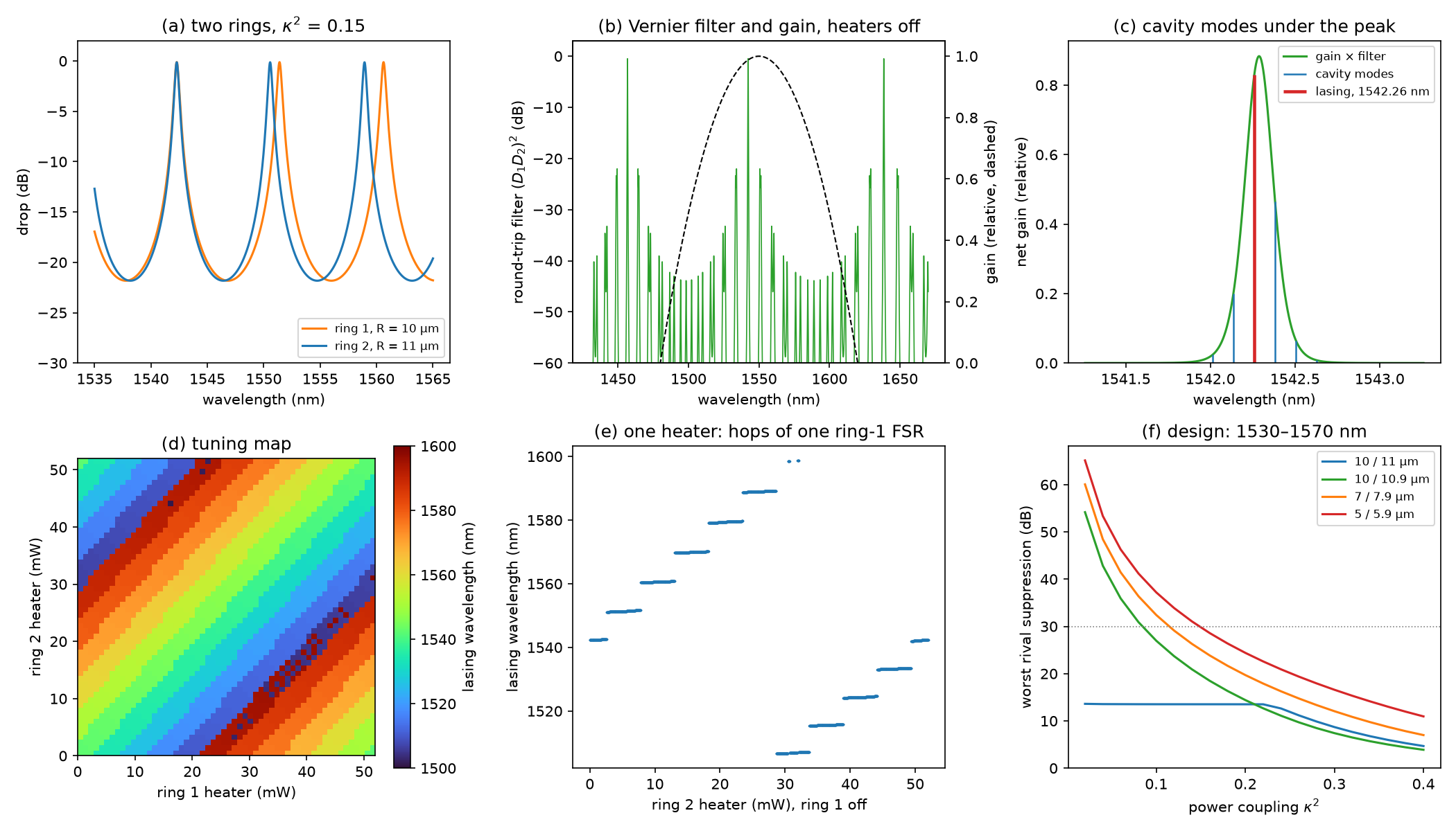
FSR = 9.148 nm for \(R\) = 10 µm and 8.316 nm for 11 µm (Worked Example 26.1: 9.148 and 8.316 nm). Ring 1 resonates at 1542.29, 1551.40 and 1560.62 nm, ring 2 at 1542.29, 1550.57 and 1558.93 nm: with the heaters off, both rings share the resonance at 1542.29 nm. With \(\kappa^2\) = 0.15 the resonances are 0.475 and 0.433 nm wide (finesse 19.3 and 19.2, Q 3250 and 3560), and drop 97 % of the light (−0.12 and −0.13 dB).
The resonances drift apart by 0.83 nm per FSR, and the spacing grows away from 1542 nm: 9.11 nm between the first two resonances of ring 1, 9.22 nm between the next two, because the FSR grows as \(\lambda^2\).
L11.2Two rings: the Vernier filter
Light that reaches the loop mirror has been dropped by both rings, and comes back through both again, so the cavity sees the product of the two drop responses, squared:
def round_trip(lam, R1, R2, p1=0.0, p2=0.0, k2=0.15):
    return (drop(lam, R1, p1, k2) * drop(lam, R2, p2, k2)) ** 2


def gain(lam):
    return np.maximum(0, 1 - ((lam - 1.55) / 0.07) ** 2)
The round trip passes light only where a resonance of each ring coincides, once every Vernier FSR, \(\mathrm{FSR}_V = \mathrm{FSR}_1\mathrm{FSR}_2/\lvert\mathrm{FSR}_1 - \mathrm{FSR}_2\rvert\) (Section 26.5). The gain chip’s gain, in the demo, is a parabola that peaks at 1550 nm and falls to zero 70 nm either side. The script finds the coincidences of the two combs over 1400–1700 nm.
\(\mathrm{FSR}_V\) = 91.5 nm and the gearing \(\mathrm{FSR}_1/(\mathrm{FSR}_1 - \mathrm{FSR}_2)\) = 11.0 (Worked Example 26.1: about 91 nm and 11). The combs coincide at 1456.7, 1542.3 and 1638.5 nm: 85.5 and 96.2 nm apart, and 11.41 THz apart in frequency both times. The gain there is 0.00, 0.99 and 0.00: only one coincidence lies in the gain window.
The Vernier FSR, like each ring’s FSR, is constant in frequency, not in wavelength: 91.5 nm is its value at 1550 nm. Here the coincidences are exact, because the radii are in the ratio 10 : 11: ring 1’s 100th resonance and ring 2’s 110th fall on the same frequency. Plot (b) of the figure shows the filter in decibels: between the coincidences, the near-misses of the two combs, one ring FSR from a coincidence, pass only about −22 dB.
L11.3Cavity modes and the lasing mode
The whole cavity, 2.5 mm of gain chip and silicon, has its own longitudinal modes \(\lambda^2/(2n_gL)\) = 0.123 nm apart, far closer than the filter’s width. cavity_modes lays them out on the demo’s grid, and lase picks the winner as the demo does: the mode with the highest net gain, gain times round-trip filter.
    filt = round_trip(modes, R1, R2, p1, p2, k2)
    v = gain(modes) * filt
    i = np.argmax(v)
    far = np.abs(modes - modes[i]) > 0.002
    j = np.argmax(np.where(far, v, 0))
The rival, j, is the best mode more than 2 nm away, on another pair of ring resonances: another supermode. Its net gain relative to the winner is the filter’s side-mode suppression. The best mode within 2 nm is a neighbouring cavity mode under the same filter peak.
812 cavity modes from 1500 to 1600 nm, 0.123 nm apart. The laser lases at 1542.26 nm (the demo reads 1542.26 nm), where the round trip through the filter loses 0.76 dB. The next-best supermode, at 1550.64 nm, is 21.2 dB down (the demo’s “next-best supermode”: −21.2 dB). The nearest cavity mode is only 2.5 dB down.
The next-best supermode sits on ring 2’s resonance at 1550.57 nm, pulled slightly towards ring 1’s at 1551.40 nm. The rivals where ring 1 is the one 0.83 nm off resonance win over those where ring 2 is, because ring 1’s resonance is the broader. The neighbouring cavity mode is weak protection: the filter peak is about 0.2 nm wide and holds several cavity modes (plot (c)). A real laser adds a phase section that slides the cavity modes so that one sits on the filter peak. The −21.2 dB is a difference in round-trip gain, set before the laser switches on; above threshold the gain clamps at the lasing mode’s loss, and the side modes’ power falls further as the laser’s power grows, so the laser’s own SMSR is larger.
L11.4Tuning with two heaters
A heater shifts a ring’s round-trip phase. A full \(2\pi\) moves its resonances by one FSR and takes \(2P_\pi\) = 52 mW with the TiN heater of Chapter 18, whatever the ring’s size, so a ring tunes at \(\mathrm{FSR}/(2P_\pi)\) nm/mW. tuning_map sweeps both heater phases over a 56 × 56 grid, as the demo does, and records the lasing wavelength at each; the script also sweeps ring 2’s heater alone, with ring 1 off, and finds where the laser hops.
def heater_mw(phase):
    return phase / np.pi * P_PI
Across the map the laser reaches 1501.0 to 1598.6 nm, 764 of the 812 cavity modes. The heaters tune ring 1 at 0.176 nm/mW and ring 2 at 0.160 nm/mW (Worked Example 26.1: 0.18 nm/mW for a ring with a 9.15 nm FSR). Heating ring 2 alone, the laser hops every 0.201π of phase, 5.23 mW, a 0.836 nm shift of ring 2 (Worked Example 26.1: 0.83 nm, about 5 mW). With ring 2 heated by 0, 5.2, 10.4 and 15.6 mW it lines up with ring 1’s resonances at 1542.29, 1551.40, 1560.62 and 1569.95 nm, and the laser lases at 1542.26, 1551.38, 1560.62 and 1569.98 nm: hops of 9.12, 9.24 and 9.36 nm (Worked Example 26.1: 9.15 nm). A whole Vernier period, 91 nm, takes 52 mW.
The 0.18 nm/mW of Worked Example 26.1 belongs to ring 1; ring 2, the one heated there, has the shorter FSR and tunes at 0.160 nm/mW, so its 0.83 nm step costs 5.2 mW rather than the 4.6 mW that 0.18 nm/mW would give. The chapter’s “about 5 mW” covers both. The hops grow with wavelength because ring 1’s FSR does.
The map (plot (d)) has two kinds of structure. Along either axis, the wavelength changes in coarse steps of one ring FSR, the Vernier gearing at work. Along diagonals where both rings move by the same wavelength, the coincidence moves continuously, and the colour changes smoothly across a stripe. Where two stripes meet, the coincidence has slid half a Vernier FSR from the gain peak, and the laser jumps by about a Vernier FSR to the next coincidence: the speckled pixels are heater settings where the two compete.
L11.5Design: radii and coupling
Now design a filter. Tune both rings onto a target wavelength with align, which returns the heater phase that puts a resonance exactly there, and compare the net gain at the target with the highest anywhere else under the gain:
    p1, p2 = align(lam_t, R1), align(lam_t, R2)
    peak = gain(lam_t) * round_trip(lam_t, R1, R2, p1, p2, k2)
    v = gain(grid) * round_trip(grid, R1, R2, p1, p2, k2)
    j = np.argmax(np.where(np.abs(grid - lam_t) > 0.002, v, 0))
This is suppression. It searches a 5 pm grid rather than the cavity modes, because whatever the cavity, some cavity mode sits close to a rival’s peak. design repeats it over a set of targets and keeps the worst case, and kappa_for_margin finds by bisection the largest coupling that keeps every rival a given number of decibels down. The design runs in three steps.
- The Vernier FSR from the tuning range. Tuned to either end of the range, the next coincidence, one Vernier FSR away in frequency, must fall outside the gain window. For 1530–1570 nm and a gain window of 1480–1620 nm that needs \(1/\lambda\) steps of at least \(1/1.48 - 1/1.57\) µm⁻¹, an \(\mathrm{FSR}_V\) of 93 nm at 1550 nm. Since \(\mathrm{FSR}_V = \lambda^2/(2\pi n_g\,\Delta R)\) = 91.5 nm·µm / \(\Delta R\), the radii may differ by at most 0.98 µm.
- The coupling from the side-mode margin. The neighbouring supermodes, one ring FSR away, see one ring detuned by \(\Delta\mathrm{FSR}\). Their suppression depends on that detuning over the ring’s linewidth, roughly \(\kappa^2\,\mathrm{FSR}/\pi\), and so on \(\kappa^2\) times the gearing \(R_2/\Delta R\): larger rings need weaker coupling.
- The costs. Weaker coupling loses more light in the filter, which raises the threshold, and narrows the peak, which separates neighbouring cavity modes better but makes the filter harder to keep aligned. Smaller rings allow stronger coupling, but bend loss, not modelled here, sets a floor near 5 µm for strip waveguides. The heater power for a full Vernier period is 52 mW whatever the radii.
For 1530–1570 nm the 10/11 µm pair fails: tuned to 1570 nm, the next coincidence at 1481.4 nm still has 4 % of the gain and is only 13.5 dB down, with \(\kappa^2\) = 0.15 or 0.10 alike. No coupling reaches 30 dB. Bringing the radii to within 0.9 µm (\(\mathrm{FSR}_V\) = 102 nm) moves it out of the window, and then a 30 dB margin over the whole range needs \(\kappa^2\) = 0.084 for 10/10.9 µm (gearing 12.1; 0.88 dB of round-trip filter loss; nearest cavity modes 11.2 dB down), 0.114 for 7/7.9 µm (gearing 8.8; 0.46 dB; 3.9 dB) and 0.148 for 5/5.9 µm (gearing 6.6; 0.26 dB; 1.3 dB).
The product \(\kappa^2 \times\) gearing comes out at about 1.0 for all three pairs: for a 30 dB margin, the coupling must fall as the gearing rises. The Chapter 26 pair, with \(\kappa^2\) = 0.15, is a 21 dB filter, and its 91.5 nm Vernier FSR is just short of a clean 40 nm range at these gain-window edges. Plot (f) shows the trade: the 10/11 µm curve is flat at 13.5 dB, set by the gain at the far coincidence, while the others rise as the coupling falls.
Exercises
- The other heater. Heat ring 1 instead, with ring 2 off:
lase(modes, p, 0.0)forpfrom 0 to \(2\pi\). Which way does the laser hop, how far, and how much power does each hop take? - Continuous tuning. Tune both rings together onto \(1542.288 + \delta\) nm with
align, for \(\delta\) from 0 to 1 nm. How much heater power does a 1 nm shift need on each ring? Does the lasing wavelength follow smoothly? - Closer radii. Use \(R_2\) = 10.5 µm. What are the Vernier FSR and the gearing, and the margin over the next supermode with the heaters off at \(\kappa^2\) = 0.15? What coupling restores the −21.2 dB of the 11 µm design, and at what cost?
- A longer cavity. Change
L_CAVat the top of the script to 5000 and run it again. What happens to the cavity-mode spacing, to the supermode margin and to the cavity-mode margins of Checkpoints C and E? Why might you still want a longer cavity? - Design for the C+L edge. Design a filter that tunes over 1520–1580 nm with every rival at least 35 dB down, for the demo’s gain window. (a) What Vernier FSR, and so what largest radius difference, does the range need? (b) Take \(\Delta R\) = 0.8 µm and \(R_1\) = 5, 7 and 10 µm: what coupling does each need (use
kappa_for_marginwithtargets = np.arange(1.520, 1.5801, 0.005)), and what round-trip filter loss do they have? (c) Which would you choose?
Answers
- Blue, by one ring-2 FSR per hop: every 0.182π of phase, 4.73 mW, a 0.832 nm shift of ring 1. With ring 1 heated by 4.73, 9.45 and 14.18 mW it lines up with ring 2’s resonances at 1534.10, 1526.00 and 1517.98 nm, and lases at 1534.13, 1526.00 and 1517.99 nm: hops of 8.13, 8.13 and 8.01 nm.
- 5.74 mW on ring 1 and 6.31 mW on ring 2 for 1 nm. The lasing wavelength follows in steps of one cavity mode, 0.123 nm: 1542.26, 1542.38, 1542.51, 1542.63 nm for \(\delta\) = 0, 0.1, 0.2, 0.3 nm, and 1543.25 nm at 1 nm. At \(\delta\) = 0.4 nm two cavity modes are within 0.2 dB of each other and the laser would hop between them. For truly continuous tuning, a phase section must move the cavity modes along with the filter.
- \(\mathrm{FSR}_V\) = 183 nm, wider than the whole gain window, and a gearing of 21. With the heaters off the laser still lases at 1542.26 nm, but the next supermode (1551.13 nm) is only 10.4 dB down: the neighbouring resonances of the two rings are now only 0.44 nm apart. \(\kappa^2\) = 0.078 restores −21.2 dB, but the round-trip filter loss grows from 0.74 to 1.94 dB.
- The modes are 0.062 nm apart (1624 of them from 1500 to 1600 nm). The supermode margin stays at −21.2 dB, since it is set by the rings alone. But the nearest cavity mode in Checkpoint C is now only 0.09 dB down, and Part E’s nearest cavity modes for 10/11 µm at \(\kappa^2\) = 0.15 rise from −4.2 to −1.2 dB: the filter barely separates neighbouring modes, and the phase section and its control must work harder. In exchange, a longer, low-loss cavity stores the light longer and narrows the linewidth (Section 25.6).
- (a) From 1580 nm the next coincidence must lie below 1480 nm: \(1/1.48 - 1/1.58\) = 0.0428 µm⁻¹, an \(\mathrm{FSR}_V\) of 102.7 nm at 1550 nm, so \(\Delta R \le\) 0.89 µm. (b) With \(\Delta R\) = 0.8 µm (\(\mathrm{FSR}_V\) = 114 nm): 5/5.8 µm needs \(\kappa^2\) = 0.101 (gearing 7.2, round-trip loss 0.38 dB, nearest cavity modes 2.7 dB down); 7/7.8 µm needs 0.077 (gearing 9.8, 0.69 dB, 7.5 dB); 10/10.8 µm needs 0.056 (gearing 13.5, 1.33 dB, 19.0 dB). \(\kappa^2 \times\) gearing is now about 0.75. (c) 7/7.8 µm is a reasonable middle: under 1 dB of filter loss, a useful cavity-mode margin, and rings large enough for low bend loss. 5 µm rings lose the least in the filter but leave the cavity modes almost unseparated and sit at the bend-loss limit; 10 µm rings lose 1.3 dB.
Going further
- Lab 12 puts lasers like this one into the budget of the reference link.
- The Vernier demo of Chapter 26 runs the same model in your browser.
- Add a phase section: shift every cavity mode by the same phase, and choose it at each tuning point so that a cavity mode sits on the filter peak. The tuning of Exercise 2 then becomes continuous.
- Combine this lab with Lab 10: give each cavity mode its own photon density and the round-trip filter as a mode-dependent loss, and compute the laser’s SMSR above threshold from multimode rate equations.