Chapter 24The Fabry–Pérot Laser and the Rate Equations
Put gain between two mirrors, pump it until gain equals loss, and the device lases.
- write the threshold condition from the round trip;
- compute the longitudinal-mode spacing and the photon lifetime;
- solve the carrier and photon rate equations for the L–I curve;
- extract the threshold current, slope efficiency and differential quantum efficiency;
- explain the temperature dependence (T₀), the turn-on delay and relaxation oscillations;
- explain how a vertical-cavity surface-emitting laser (VCSEL) works: Bragg mirrors, the oxide aperture, its sub-milliampere threshold and its thermal roll-over, and why VCSELs dominate short-reach multimode links.
What sets a laser’s threshold current and slope efficiency?
24.1The optical cavity
The simplest laser is a semiconductor waveguide cleaved at both ends. The cleaved facets reflect \(R = ((n - 1)/(n + 1))^2 \approx 0.30\) for an effective index near 3.4 (0.32 for 3.6, the round value this chapter and its demo use), and form a Fabry–Pérot cavity of length \(L\). Light makes round trips; the cavity supports longitudinal modes wherever a round trip is a whole number of wavelengths, spaced by
\[\Delta\lambda = \frac{\lambda^2}{2n_gL},\]0.83 nm for a 400 µm cavity with \(n_g = 3.6\). Light leaks out through the mirrors at an average rate per unit length, the mirror loss,
\[\alpha_m = \frac{1}{2L}\ln\frac{1}{R_1R_2},\]and is absorbed inside at the internal loss \(\alpha_i\). A photon survives in the cavity for the photon lifetime \(\tau_p = 1/[v_g(\alpha_i + \alpha_m)]\): a few picoseconds.
24.2Threshold
The laser reaches threshold when the gain over a round trip makes up exactly for the losses: the light returns to where it started with the same amplitude and phase. For the amplitude:
Above threshold the gain cannot grow further: any extra gain would make the light grow without limit, and the stimulated emission it causes pulls the carrier density back down. The gain and the carrier density are clamped at their threshold values, and every additional injected carrier becomes a photon.
24.3Rate equations
The laser’s behaviour follows from two coupled equations, one for the carrier density \(N\) and one for the photon density \(S\) in the mode [4]:
Carriers arrive with the current (a fraction \(\eta_i\), the injection efficiency, reaching the active volume \(V\)), recombine through \(R(N) = AN + BN^2 + CN^3\) (Chapter 23), and are consumed by stimulated emission. Photons are created by stimulated emission and a small fraction \(\beta\) of the spontaneous emission that falls into the mode, and escape after \(\tau_p\). The gain \(g(N)\) is the fitted logarithm \(g_0\ln(N/N_\mathrm{tr})\), divided by \(1 + \varepsilon S\) for gain compression at high power.
In steady state above threshold, \(N = N_\mathrm{th}\) and the photon density grows linearly with current:
\[I_\mathrm{th} = \frac{qV}{\eta_i}\,R(N_\mathrm{th}), \qquad P_\mathrm{out} = \eta_d\,\frac{h\nu}{q}\,(I - I_\mathrm{th}), \qquad \eta_d = \eta_i\,\frac{\alpha_m}{\alpha_i + \alpha_m}.\]The differential quantum efficiency \(\eta_d\) is the fraction of extra electrons that become photons leaving through the mirrors. It is the injection efficiency times the share of the cavity loss that is useful output.
Try it. Change the current, the cavity length, the front-facet reflectivity and the temperature. The L–I curve, the switch-on transient and the spectrum follow from the rate equations.
24.4The L–I curve and efficiency
The demo’s laser has a 2 µm × 50 nm active region (\(V = 4\times10^{-11}\) cm³), \(\Gamma = 0.06\), \(\alpha_i = 15\) cm⁻¹ and cleaved facets. Then \(\alpha_m = \ln(1/0.32^2)/(2 \times 0.04\ \mathrm{cm}) = 28.5\) cm⁻¹ and \(g_\mathrm{th} = (15 + 28.5)/0.06 = 725\) cm⁻¹, so \(N_\mathrm{th} = 2\times10^{18}\,e^{725/1500} = 3.24\times10^{18}\) cm⁻³. With the recombination coefficients of Chapter 23, \(R(N_\mathrm{th}) = 2.4\times10^{27}\) cm⁻³ s⁻¹ and
\[I_\mathrm{th} = \frac{1.6\times10^{-19} \times 4\times10^{-11} \times 2.4\times10^{27}}{0.8} = 19\ \mathrm{mA}.\]Above threshold \(\eta_d = 0.8 \times 28.5/43.5 = 0.52\), shared between the two facets, so the slope efficiency per facet is \(0.26 \times 0.80\ \mathrm{V} = 0.21\) W/A. At 50 mA, each facet emits about 6.5 mW. With a 0.85 V diode drop and 5 Ω of series resistance, the electrical input is 55 mW, a wall-plug efficiency of about 23 % for both facets together.
The design levers follow from these formulas. A shorter cavity has more mirror loss: higher threshold gain, but less volume to pump, and a higher \(\eta_d\). A high-reflection coating on the rear facet sends most of the light out of the front and lowers the threshold. Lower internal loss improves everything. And a smaller, better-confined active region with more differential gain (quantum wells) lowers the threshold current.
24.5Temperature
Threshold rises roughly exponentially with temperature,
\[I_\mathrm{th}(T) = I_\mathrm{th}(T_\mathrm{ref})\,e^{(T - T_\mathrm{ref})/T_0},\]with a characteristic temperature \(T_0\) of 50–70 K for InGaAsP lasers. That is the combined effect of Fermi smearing, Auger recombination and carrier leakage (Chapter 23). The demo uses \(T_0 = 60\) K: from 25 °C to 85 °C the threshold grows by a factor of \(e\), from 19 to 52 mA. Self-heating from the drive current adds to the ambient temperature. When the threshold rises faster than the current, the output stops growing and falls: thermal roll-over, especially severe for lasers on silicon-on-insulator, where the buried oxide traps heat (Chapter 27). The gain peak also moves, by about 0.5 nm/K, and with it the lasing wavelength of a Fabry–Pérot laser.
24.6Transients
When the current is switched on, the laser does not respond at once. First the carriers must build up to threshold, which takes the turn-on delay
\[\tau_d \approx \tau_n\ln\frac{I}{I - I_\mathrm{th}},\]with \(\tau_n\) the carrier lifetime near threshold, about 1.35 ns here, giving 0.9 ns at 40 mA. Then photons and carriers overshoot and ring as they exchange energy at the relaxation-oscillation frequency of a few gigahertz, before settling. These dynamics set how fast a laser can be modulated directly (Chapter 25).
24.7The Fabry–Pérot spectrum
The gain spectrum is tens of nanometres wide, and the modes are less than a nanometre apart, so many modes see nearly the same gain. A Fabry–Pérot laser runs on several longitudinal modes at once, and its spectrum shifts and hops with temperature and current. Over fibre, the spread of wavelengths turns into pulse spreading through dispersion; in WDM, it wastes the spectrum. Single-frequency lasers add a wavelength-selective element, a grating or a ring, that favours one mode (Chapter 26).
24.8The vertical-cavity surface-emitting laser
Stand the cavity on end and shrink it to one wavelength, and the result is a vertical-cavity surface-emitting laser (VCSEL). The mirrors, the cavity and the quantum wells are grown as one stack of layers on a GaAs wafer, and the light leaves through the top surface (Figure 24.1). It is still a Fabry–Pérot laser, and every formula of this chapter applies to it, but its numbers are so different that it behaves like another device. Most short optical links, the multimode-fibre connections inside data centres and supercomputers, start in an 850 nm VCSEL [79, 76].
Mirrors. The gain region is three quantum wells, 24 nm of material, crossed once per pass. A pass through so little material amplifies the light by well under 1 %, so the mirrors must reflect more than 99 %, which no cleaved facet can. Each mirror is a distributed Bragg reflector (DBR): quarter-wave layers of AlGaAs with low and high aluminium content, whose small reflections add in phase, as in the Bragg gratings of Chapter 13. With indices of 3.52 and 3.05 at 850 nm, a transfer-matrix calculation gives a reflectance of 99.62 % for 20 pairs and 99.983 % for 34. The upper mirror is doped p-type and is the output; the lower is doped n-type and sits on the substrate. Because each layer reflects only a little, the light reaches about 0.41 µm into each mirror before it turns back. The effective cavity is therefore 1.08 µm long, although the cavity layer itself is only one wavelength in the material, 0.25 µm thick (Figure 24.1b).
Aperture. One layer of nearly pure AlAs, in the p-mirror just above the cavity, is oxidised sideways from the wall of the etched mesa in hot steam. The oxidation is stopped while an unoxidised island a few micrometres across remains in the middle: the oxide aperture. Aluminium oxide is an insulator, so the aperture funnels the current into the centre, and its lower refractive index guides the light there too. Carriers and photons are confined to the same small disc.
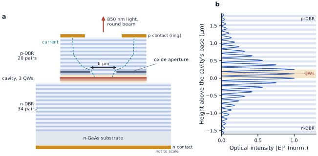
figsrc/ch2x_lasers.py.The VCSEL of Figure 24.1 has a one-wavelength Al₀.₃Ga₀.₇As cavity with three 8 nm quantum wells. The values in brackets are those of the 400 µm laser of Worked Example 24.1.
- Losses. \(\alpha_m = \ln[1/(0.99622 \times 0.99983)]/(2 \times 1.08\ \mu\mathrm{m}) = 18.4\) cm⁻¹ (28.5), almost all of it through the top mirror (17.6 cm⁻¹). The doped mirrors absorb \(\alpha_i \approx 20\) cm⁻¹, and with \(n_g = 3.8\) the photon lifetime is 3.3 ps (2.8 ps).
- Gain needed. The wells fill 24 nm of the 1.08 µm, sit on a peak of the standing wave (a factor of 1.8) and overlap 80 % of the mode sideways, so \(\Gamma = 0.032\) (0.06) and \(g_\mathrm{th} = 38.4/0.032 \approx 1200\) cm⁻¹ (725). Strained quantum wells provide it: with \(g_0 = 3000\) cm⁻¹, \(N_\mathrm{tr} = 1.8\times10^{18}\) cm⁻³ and the gain peak slightly off the cavity resonance (see below), \(N_\mathrm{th} = 3.1\times10^{18}\) cm⁻³.
- Threshold. The active volume is \(\pi(3\ \mu\mathrm{m})^2 \times 24\ \mathrm{nm} = 6.8\times10^{-13}\) cm³, 59 times smaller than the edge emitter’s. With GaAs recombination coefficients (weaker Auger recombination than InGaAsP), \(I_\mathrm{th} = qVR(N_\mathrm{th})/\eta_i = 0.18\) mA (19 mA), a threshold current density of 0.63 kA/cm².
- Efficiency. \(\eta_d = 0.8 \times 17.6/38.4 = 0.37\) through the top mirror; with 1.46 eV photons the slope efficiency is 0.53 W/A. At 5 mA the laser emits 2.6 mW from 1.95 V: a wall-plug efficiency of 26 %.
- Modes. Longitudinal modes are \(\lambda^2/(2n_gL_\mathrm{eff}) = 88\) nm apart, wider than the whole gain spectrum, so only one fits: a VCSEL has a single longitudinal mode by construction. An aperture this wide does guide several transverse modes, which suits multimode fibre.
The threshold is an ideal estimate that ignores current spreading around the edge of the aperture; measured thresholds of such devices are a fraction of a milliampere [79].
Temperature and roll-over. Two things set a VCSEL’s temperature behaviour. The first is alignment. The single cavity mode moves only with the refractive index, about 0.065 nm/K, while the gain peak moves with the band gap, about 0.30 nm/K. Designers therefore place the gain peak on the short-wavelength side at room temperature, 12 nm short in this example, so that peak and resonance meet when the device is warm, here at 76 °C. Together with the rise of the transparency density, this makes the threshold lowest near 45 °C and only 15 % higher at 85 °C than at 25 °C, where the edge emitter’s threshold (\(T_0 = 60\) K) grows 2.7 times (Figure 24.2b). The second is heat. The current crosses dozens of mirror interfaces, so the series resistance is high (80 Ω here), and the heat leaves through a footprint a few micrometres across, so the thermal impedance is high too (2.5 K/mW). At 14 mA the junction runs 79 K above ambient, the gain has slid off the resonance, carriers leak over the barriers, and the output rolls over at 6.4 mW. At 85 °C ambient it peaks at only 2.9 mW, at 8.4 mA (Figure 24.2a). VCSELs therefore run at a few milliamperes, well below roll-over.
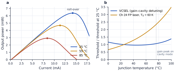
figsrc/ch2x_lasers.py.Why VCSELs rule short links. Several advantages add up [79, 93]:
- Low current. A VCSEL is modulated at tens of gigabits per second from a few milliamperes and about 2 V, some 10 mW, while an edge emitter needs tens of milliamperes (Chapter 25 compares their speed).
- Testing on the wafer. It emits from the surface, so every laser can be tested before the wafer is diced; an edge emitter must first be cleaved into bars to expose its facets.
- A round beam. The output is a circular, weakly diverging beam that couples into the 50 µm core of a multimode fibre with loose alignment tolerances, so assembly is cheap.
- Arrays. Lasers sit side by side on the wafer: rows at the pitch of a fibre ribbon carry parallel links, and two-dimensional arrays are possible.
- A cheap receiver. 850 nm light is detected by GaAs or even silicon photodiodes (Chapter 21).
The price is reach. The many modes of a multimode fibre travel at different speeds, and this modal dispersion limits links to a few hundred metres at 10 Gb/s and less at higher rates [93]. Longer and WDM links use single-mode lasers at 1310 and 1550 nm, where VCSELs are much harder to build: the InP-based mirror materials offer little index contrast and conduct heat poorly. And an 850 nm VCSEL cannot feed a silicon waveguide, which absorbs at that wavelength (Chapter 27).
- The UBC ELEC 413 course designs and measures semiconductor lasers on the SiEPIC laser-integration runs, and publishes the designs and data openly [12].
Reading
- [4] Larry A. Coldren, Scott W. Corzine and Milan L. Mašanović. Diode Lasers and Photonic Integrated Circuits, 2nd edition. Wiley, 2012.
- [5] Anthony E. Siegman. Lasers. University Science Books, 1986.
- [12] SiEPIC program, University of British Columbia. UBC ELEC 413 Semiconductor Lasers: design submissions and measurement data (MIT licence). https://github.com/SiEPIC/UBC-ELEC413-2025Fall
- [79] Sam Palermo. “Lecture 8: VCSEL TXs.” ECEN 721: Optical Interconnects Circuits and Systems, Texas A&M University, Spring 2026. https://people.engr.tamu.edu/spalermo/ecen689_oi/lecture8_ee721_vcsel_tx.pdf
- [93] Sam Palermo. “Lecture 2: Optical Channels.” ECEN 721: Optical Interconnects Circuits and Systems, Texas A&M University, Spring 2026. https://people.engr.tamu.edu/spalermo/ecen689_oi/lecture2_ee721_optical_channels.pdf
- Threshold: \(\Gamma g_\mathrm{th} = \alpha_i + \ln(1/R_1R_2)/(2L)\); above it the gain and carrier density clamp.
- Modes are spaced by \(\lambda^2/(2n_gL)\); photons live for \(\tau_p = 1/[v_g(\alpha_i + \alpha_m)]\), a few picoseconds.
- \(I_\mathrm{th} = qVR(N_\mathrm{th})/\eta_i\) and \(\eta_d = \eta_i\alpha_m/(\alpha_i + \alpha_m)\): 19 mA and 0.21 W/A per facet for the 400 µm example.
- Threshold grows as \(e^{T/T_0}\) (\(T_0\) ≈ 60 K); self-heating causes roll-over.
- Turn-on delay and relaxation oscillations limit direct modulation; Fabry–Pérot lasers are multimode.
- A VCSEL is a one-wavelength cavity between Bragg mirrors (99.62 % and 99.983 % for 20 and 34 pairs), with an oxide aperture confining current and light: 59 times less active volume, a 0.18 mA threshold, 0.53 W/A and one longitudinal mode in the example.
- Gain–cavity detuning keeps a VCSEL’s threshold nearly constant with temperature, but self-heating rolls its output over (6.4 mW at 25 °C, 2.9 mW at 85 °C). Low current, wafer testing, round beams and arrays make it the source of short multimode links.